3 Phase Isolation Transformer, 4 kVA-300 kVA

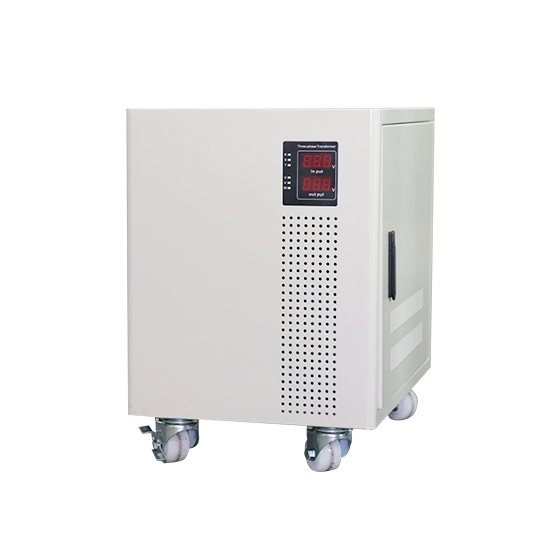
3 phase isolation transformer front side
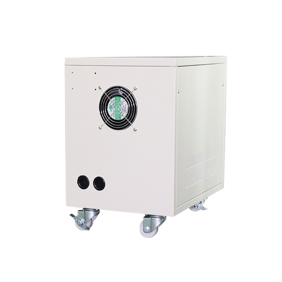
3 phase isolation transformer behind side
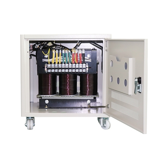
3 phase isolation transformer inside

Three-phase isolation transformers are available to meet special voltage requirements, winding configurations, mounted terminals, unusual sizes and shapes, providing capacities up to 300 kVA. have been designing and building three-phase isolation transformers for over a decade and have supplied in some challenging applications.

Specification

Model ATO-T-SG
Phase 3 phase
Capacity 4 kVA to 300 kVA
Primary Voltage 0V to 1140V (customized)
Secondary Voltage 0V to 1140V (customized)
Frequency 50Hz / 60 Hz
Winding Material Aluminium/copper wire customized
Work Efficiency ≥95%
Insulation Resistance ≥50 MΩ
Electrical Strength 3000V AC/1 min
Noise <35-65 dB (1 meter)
Insulation Grade H level

(Note: If you want to know more about 3 phase isolation transformer specification, please check in catalogue.)

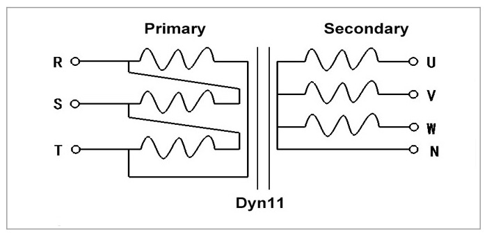
Schematic Diagram


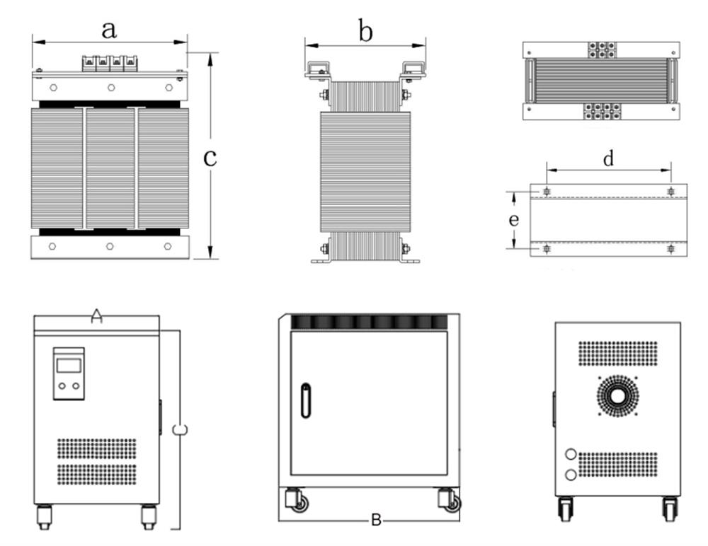
Dimension


Aluminium Wire Transformer Size
  • Open type: a*b*c=380*200*380mm
  • Mouting size: d*e=260*110mm
  • Protected type: A*B*C=300*440*500mm
Copper Wire Transformer Size
  • Open type: a*b*c=300*170*310mm
  • Mouting size: d*e=180*140mm
  • Protected type: A*B*C=300*440*500mm

Advantages

Source Factory

Quality Assurance

Excellent Material

Fast Delivery

Multiple Models

Great Service

3 Phase Isolation Transformer Working Conditions

As is known to all, there are many electrical equipment must be in a rated voltage to work properly. However, the isolation transformer also needs to have a working environment to be able to work normally, so what kind of operating condition does the 3 phase isolation transformer need?
  1. Temperature. The air temperature should not exceed 40 ℃ when operating the isolation transformer.
  2. Humidity. The relative humidity of the air is not more than 85%.
  3. Altitude. No more than 2000 meters above sea level. (Isolation transformer is also not able to work in a long-term rain and snow environment.)
  4. Non-explosion environment. The isolation transformer must be operated in an environment without explosion risk.
Focus on customize

Focus on Customize

ATO provides complete design, engineering, and manufacturing services to supply our customers with the finest, most efficient and cost-effective single phase and 3 phase isolation transformers. ATO step up and step down transformer design and manufacturing capabilities are some of the broadest in the industry. Our Chinese engineers understand environmental compliance concerns and have a comprehensive working knowledge of all applicable market trends. Our goal is to deliver excellent quality products accompanied by top-of-the-line customer service. Whether using the finest techniques to ensure productivity or finding the most cost-effective freight carriers, we got you!

FAQs

How to wire a 3 phase isolation transformer?

A 3 phase isolation transformer is typically wired by connecting the primary and secondary windings of each single phase transformer in a specific configuration. The most common wiring configurations for a three phase isolation transformer are:
  • Delta-Delta connection: The primary and secondary windings are connected in a delta configuration, forming a closed loop.
  • Wye-Wye connection: The primary and secondary windings are connected in a wye configuration, forming a star or neutral point.
  • Delta-Wye connection: The primary winding is connected in a delta configuration, while the secondary winding is connected in a wye configuration.
  • Wye-Delta connection: The primary winding is connected in a wye configuration, while the secondary winding is connected in a delta configuration.

The specific wiring configuration depends on the system requirements and the desired output voltage and current relationships.

Difference between 3 phase isolation transformer and 3 phase autotransformer

A 3 phase isolation transformer and a 3 phase autotransformer are two different types of transformers used in electrical power systems. Here are the key differences between them:
  • Construction: The construction of a three-phase isolation transformer involves separate primary and secondary windings that are electrically isolated from each other. In contrast, a three-phase autotransformer has a single winding that serves as both the primary and secondary winding, with various taps along its length to provide different voltage levels.
  • Voltage Transformation: An isolation transformer provides complete electrical isolation between the primary and secondary windings, meaning there is no direct electrical connection between them. It can provide step-up or step-down voltage transformation by adjusting the number of turns in each winding. On the other hand, an autotransformer has a common winding shared by both the primary and secondary sides. Voltage transformation in an autotransformer is achieved by tapping different points along the winding, resulting in a voltage ratio between the input and output.
  • Voltage Regulation: Isolation transformers are primarily used for electrical isolation and noise reduction purposes. They do not offer voltage regulation capabilities, meaning the output voltage is dependent on the input voltage and the transformer turns ratio. Autotransformers, on the other hand, can provide voltage regulation since they have multiple taps along the winding that allow for adjusting the voltage levels.
  • Efficiency: Autotransformers tend to be more efficient compared to isolation transformers. This is because they have a single winding and, therefore, have fewer losses associated with the separate windings and insulation found in isolation transformers.
  • Size and Cost: Isolation transformers are generally larger and more expensive than autotransformers due to their construction with separate windings and insulation. Autotransformers, being simpler in design, tend to be smaller and more cost-effective.

What is the insulation level of 3 phase isolation transformer?

The insulation level of a three phase isolation transformer refers to its ability to withstand high voltage without experiencing electrical breakdown or insulation failure. Insulation levels are typically specified in terms of voltage ratings.
In general, the insulation level of a transformer is determined by its operating voltage and the desired safety margins. The voltage rating indicates the maximum voltage that the insulation can safely withstand before breakdown occurs.
The insulation level of a three phase isolation transformer is usually specified in terms of the transformer's basic insulation level (BIL). BIL represents the impulse voltage level that the transformer's insulation can withstand without breakdown. Impulse voltages can occur due to lightning strikes or other electrical disturbances.
The BIL rating of a transformer is typically expressed in kilovolts (kV) and is based on standard levels, such as 10 kV, 20 kV, 30 kV, and so on. The specific BIL rating depends on the application and the voltage level of the system where the transformer is installed.
To determine the insulation level of a specific 3 phase isolation transformer, you would need to refer to the manufacturer's specifications or consult the transformer's technical documentation. The manufacturer will provide the BIL rating and any other relevant insulation details for the transformer model in question.

How does a 3 phase isolation transformer provide electrical isolation?

A 3 phase isolation transformer provides electrical isolation by using separate windings for the primary and secondary sides of the transformer. Each winding is physically and electrically insulated from the others. This isolation prevents direct electrical contact and the transfer of electrical energy between the primary and secondary sides.Here's a step-by-step explanation of how a three phase isolation transformer achieves electrical isolation:
  • Separate Windings: The transformer has three separate primary windings and three separate secondary windings, one for each phase. These windings are physically isolated from each other and wound on the transformer core.
  • No Electrical Connection: There is no direct electrical connection between the primary and secondary windings. Each winding is electrically isolated, and there are no physical conductive paths between them.
  • Magnetic Field Induction: When 3 phase alternating current (AC) is applied to the primary windings, it generates a magnetic field in the transformer core. This magnetic field induces a voltage in the secondary windings.
  • Voltage Transformation: The induced voltage in the secondary windings is proportional to the turns ratio between the primary and secondary windings. The transformer can step up or step down the voltage depending on the winding configuration.
  • Electrical Isolation: Due to the physical separation and lack of electrical connection between the windings, the voltage on the primary side does not directly transfer to the secondary side. The magnetic coupling between the windings allows for energy transfer but maintains electrical isolation.
  • Isolation Benefits: The electrical isolation provided by the transformer offers several advantages. It protects equipment and personnel from electric shock, prevents ground loops, reduces noise and interference, and isolates sensitive equipment from voltage fluctuations or disturbances on the primary side.

By using separate windings and maintaining electrical isolation, a three-phase isolation transformer ensures that electrical energy does not pass directly between the primary and secondary sides. This feature is crucial in various applications where safety, equipment protection, and electrical isolation are necessary.

Can a 3 phase isolation transformer be used to convert 3 phase power to 1 phase power?

Yes, a 3 phase isolation transformer can be used to convert three phase power to single phase power. The isolation transformer provides electrical isolation between the input and output, and it can be designed to convert the voltage levels and phase configurations.
To convert 3 phase power to single-phase power, the three phase input is typically connected to the primary winding of the isolation transformer, while the secondary winding is configured to provide a single phase output. The specific connection depends on the desired voltage and phase configuration of the single-phase output.
For example, if you want to convert a three-phase, three-wire input to a single-phase, two-wire output, you can use the primary winding of the isolation transformer to connect the three-phase input, and connect only one of the secondary winding phases to the load.
It's important to note that the power rating of the isolation transformer should be suitable for the load requirements of the single-phase system. Also, depending on the specific application, additional circuitry such as rectifiers or phase shifting components may be required to achieve the desired voltage and phase configuration.
If you are planning to use an isolation transformer for a specific application, it is recommended to consult with our qualified electrical engineer to ensure proper configuration and compatibility with your system requirements.

What are the common ratings of 3 phase isolation transformers?

The common ratings of 3 phase isolation transformers can vary depending on the specific application and the country or region where they are used. Here are a few common ratings for 3 phase isolation transformers:
  • Power Rating: The power rating of 3 phase isolation transformers is typically expressed in kilovolt-amperes (kVA) or megavolt-amperes (MVA). Common power ratings include 5 kVA, 10 kVA, 25 kVA, 50 kVA, 100 kVA, 250 kVA, 500 kVA, 1 MVA, 5 MVA, etc. Higher power ratings are also available for industrial and utility-scale applications.
  • Voltage Rating: The voltage rating of a 3 phase isolation power transformer refers to the maximum voltage that it can handle. Common voltage ratings include 208V, 240V, 480V, 600V, 2.4 kV, 4.16 kV, 6.6 kV, 11 kV, 13.8 kV, 33 kV, etc. The specific voltage rating depends on the requirements of the electrical system in which the transformer will be used.
  • Frequency: 3 phase isolation transformers are designed to operate at specific frequencies. The most common frequency ratings are 50 Hz and 60 Hz, which correspond to the standard power system frequencies in different regions of the world.
  • Cooling Method: Transformers may have different cooling methods, such as air-cooled or liquid-cooled. The cooling method affects the transformer's ability to dissipate heat generated during operation and can vary based on the transformer's power rating.
These are just some common ratings for 3 phase isolation transformers. It's important to consult with our qualified electrical engineer to determine the appropriate ratings for your specific application, as requirements can vary based on factors such as load, voltage, current, and environmental conditions.