Split Phase Isolation Transformer, 1 kVA to 30 kVA
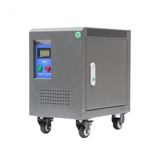
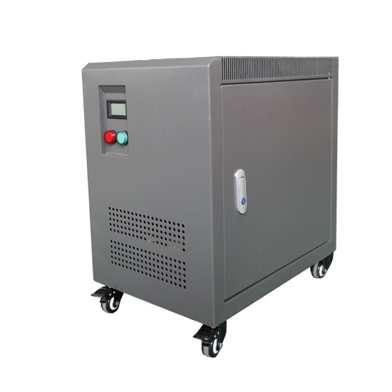
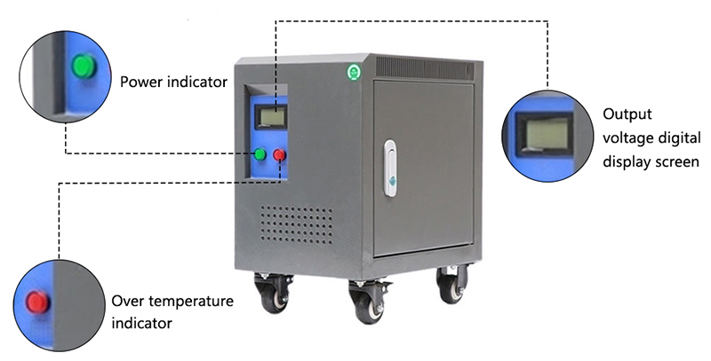
Split phase isolation transformer front side
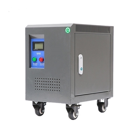
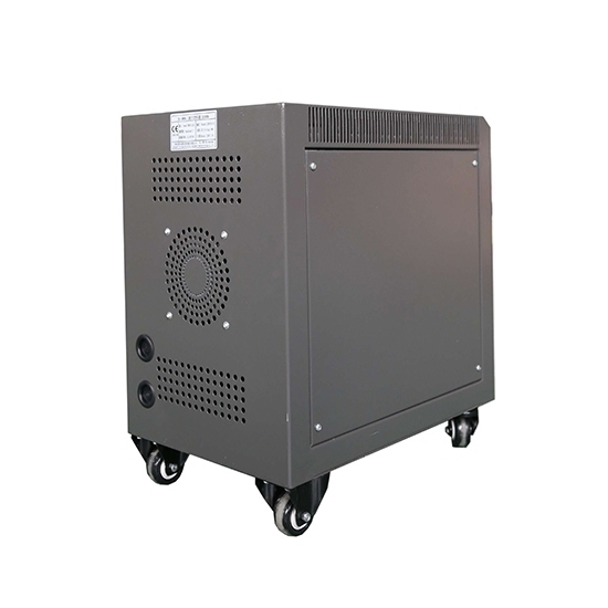
Split phase isolation transformer behind side
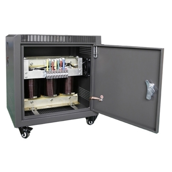
Split phase isolation transformer inside

We are committed to producing high-quality split-phase isolation transformers with a capacity range up to 30KVA. Split-phase isolation transformers undergo strict quality control and testing to ensure compliance with international standards and specifications. Whether used for power transmission and distribution, or powering electronic equipment, our split-phase transformers provide a stable and reliable energy conversion solution.

Specification

Model ATO-DGS
Phase Single phase to split phase
Capacity 1 kVA to 30 kVA (customized)
Primary Voltage 1 Phase / 2 phase 110 to 480V (customized)
Secondary Voltage 110V-480V (customized)
Frequency 50/60Hz
Winding Material Aluminum/copper wire (customized)
Work Efficiency ≥95%
Insulation Resistance ≥50 MΩ
Electrical Strength 2000V AC/1 min
Noise ≤35dB (1 meter)
Insulation Grade Grade B (130℃), Grade F (155℃), Grade H (180℃)
Cooling Method Natural or air cooling

(Note: If you want to know more about split phase isolation transformer specification, please check in catalogue.)

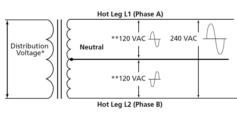
Schematic Diagram

Dimension
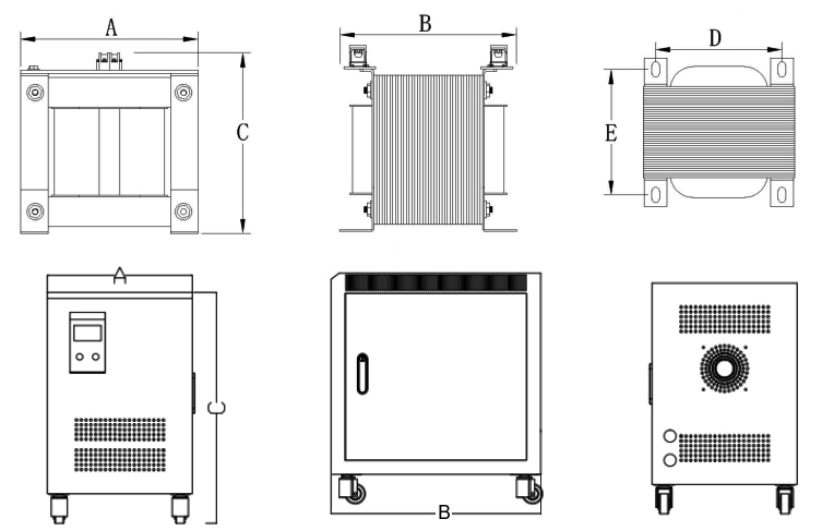
Aluminium Wire Transformer Size
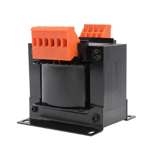
  • Open type: a*b*c=240*240*260mm
  • Mouting size: D*E=180*170mm (aperture: 20*10mm)
  • Protected type: A*B*C=300*440*500mm
Copper Wire Transformer Size
  • Open type: a*b*c=240*230*260mm
  • Mouting size: 180*160mm (aperture: 20*10mm)
  • Protected type: A*B*C=380*530*560mm

Advantages

Source Factory

Quality Assurance

Excellent Material


Fast Delivery

Multiple Models

Great Service

Split Phase Isolation Transformer Features

  • Scientific and reasonable design, the voltage variation rate is controlled within 1-1.5%.
  • Split phase isolation transformer is made of high quality new silicon steel sheet, which can effectively reduce iron loss and improve efficiency.
  • The transformer is made of high temperature resistance and high quality wire, which greatly improves efficiency.
  • Class H insulation, high temperature resistant insulation material, improves the high pressure strength, prolongs the service life.
  • The isolation transformer has beautiful appearance design, large power density, small volume and high space utilization rate.
FAQs

Can a split-phase transformer be used with both resistive and inductive loads?

Yes, a split-phase transformer can be used with both resistive and inductive loads. A split-phase transformer is a type of single-phase transformer that has a center-tapped secondary winding, which creates two separate phases with a phase shift of 180 degrees between them. The center tap is typically connected to a neutral wire, while the two ends of the winding are connected to the line wires.

Resistive loads, such as incandescent bulbs or electric heaters, draw current in proportion to the applied voltage. When  connected to one of the line wires and the neutral wire, they receive the full voltage and function as expected.
Inductive loads, on the other hand, have a property called reactance, which causes them to draw current that leads or lags the applied voltage. This reactive component is typically seen in devices like electric motors, transformers, or
solenoids. When an inductive load is connected to the split-phase transformer, the voltage across the load will depend on the impedance of the load and the phase relationship with the voltage supplied.

So, a split-phase transformer can accommodate both resistive and inductive loads. However, it's important to consider the characteristics of the specific load and how it interacts with the transformer's output voltage and phase shift. Proper
sizing and selection of the transformer are crucial to ensure compatibility and optimal performance for the connected
loads.

How to calculate the power rating for a split-phase transformer?

To calculate the power rating for a split-phase transformer, you need to consider the following factors:

  • Primary Voltage (Vp): The voltage supplied to the primary winding of the transformer.
  • Secondary Voltage (Vs): The desired voltage output from the secondary winding of the transformer.
  • Current (I): The current flowing through the secondary winding.
  • Power Factor (PF): The power factor of the load connected to the secondary winding. It represents the efficiency of power transfer. The power rating (P) can be calculated using the formula: P = Vs * I * PF

Here's a step-by-step guide on how to calculate the power rating for a split-phase transformer:

  1. Determine the desired secondary voltage (Vs) required for your application.
  2. Determine the current (I) that will flow through the secondary winding. This can be determined by knowing the load  connected to the secondary winding. If you know the power (P) required by the load, you can use the formula: I = P / (Vs * PF)

Note: The power factor (PF) can vary depending on the type of load. It is typically specified in the load's specifications or can be assumed based on the type of load (e.g., motors typically have a power factor around 0.8 to 0.9). Once you have determined the secondary voltage (Vs) and current (I), you can calculate the power rating (P) using the formula: P = Vs * I * PF

Substitute the values of Vs, I, and PF into the formula to calculate the power rating in watts (W) or kilowatts (kW), depending on the magnitude of the power.

Note: The power rating calculated using this method represents the maximum power that the transformer can handle safely. It's important to choose a transformer with a power rating equal to or higher than the calculated value to ensure proper operation and avoid overloading the transformer.

How are the primary and secondary windings connected in a split-phase transformer?

In a split-phase transformer, the primary and secondary windings are connected in a specific configuration to create a split-phase electrical system. This type of transformer is commonly used in residential electrical distribution systems to provide single-phase power for household applications.

The primary winding of a split-phase transformer consists of a center-tapped winding, meaning it has a tap or connection point at its center. This tap divides the primary winding into two equal sections. The primary winding is typically connected to the utility power lines.

The secondary winding of the split-phase transformer is composed of two separate windings, which are connected to the primary winding. One end of each secondary winding is connected to one of the outer terminals of the primary winding, while the other ends of the secondary windings are connected together. The center tap of the primary winding is also connected to this common connection point of the secondary windings.

This configuration creates two distinct voltage outputs from the secondary windings. The voltage between each end of the secondary windings and the center tap is referred to as the line voltage, which is typically 120 volts in residential applications. The voltage between the two ends of the secondary windings (without referencing the center tap) is referred to as the phase voltage and is typically 240 volts.

By utilizing this split-phase configuration, the transformer provides two voltage levels suitable for powering various appliances and equipment in a household. The line voltage is used for smaller loads, while the higher phase voltage is used for larger appliances such as electric stoves, dryers, and air conditioning units.

Is split-phase the same as two phase?

No, split-phase and two-phase are not the same. Split-phase refers to a type of single-phase electrical power distribution commonly used in residential and small commercial applications. It involves splitting a single-phase electrical supply into two separate phases, each with a 180-degree phase difference, to provide two live conductors. This split allows for the use of 120-volt circuits and 240-volt circuits in a single-phase system.

On the other hand, two-phase refers to a type of electrical power distribution system that has two separate phases, typically denoted as phase A and phase B. Unlike split-phase, two-phase systems are not commonly used in modern power distribution. They were historically used in some early electrical systems but have been largely phased out in favor of three-phase systems, which are more efficient and balanced.

To summarize, split-phase is a type of single-phase system that splits the voltage into two separate phases, while two-phase refers to a system with two distinct phases.

Can a split-phase transformer be used with both resistive and inductive loads?

Yes, a split-phase transformer can be used with both resistive and inductive loads.

A split-phase transformer is a type of single-phase transformer that is designed to provide two separate 120V AC outputs, typically referred to as the "hot" and "neutral" wires, which are 180 degrees out of phase with each other. This configuration allows for the creation of a split-phase electrical system commonly used in residential and light commercial applications.

In such a system, resistive loads, such as incandescent lights or electric heaters, draw current in a purely resistive manner. They consume power without any phase shift between voltage and current.

Inductive loads, on the other hand, have components that store energy in magnetic fields, such as motors, transformers, or some types of lighting. Inductive loads introduce a phase shift between voltage and current due to the energy storage and release processes. The current in an inductive load lags behind the voltage waveform.

A split-phase transformer is capable of supplying power to both resistive and inductive loads because it generates a sinusoidal voltage waveform with two separate 120V outputs. This waveform can be used to power a wide range of electrical devices, including both resistive and inductive loads.

However, it is important to properly size the split-phase transformer for the intended load. The transformer's kVA (kilovolt-ampere) rating should be chosen to accommodate the total power requirements of the connected loads, considering both the resistive and inductive components. Additionally, if the inductive loads are significant, it may be necessary to consider power factor correction techniques to improve the efficiency of the overall system.

In summary, a split-phase transformer can indeed be used with both resistive and inductive loads, as long as the transformer is appropriately sized for the total power demands and considerations are made for any power factor issues that may arise.

What is the purpose of the center tap in a split-phase transformer?

In a split-phase transformer, the center tap serves an important purpose in creating a split-phase electrical system. The split-phase system is commonly used in residential and small commercial applications, where 120/240 volts is required.

The center tap, also known as the neutral tap, is connected to the midpoint of the secondary winding of the transformer. This secondary winding is divided into two equal sections, creating two separate voltage outputs. The center tap is connected to the neutral wire, while the other two ends of the winding provide the hot wires, each with a voltage of 120 volts relative to the neutral.

The purpose of the center tap is to create a reference point or a neutral point for the electrical system. It allows the distribution of power across a 120/240-volt system, where most electrical loads operate at 120 volts. By providing a neutral point, the enter tap enables the connection of electrical devices that require 240 volts, such as large appliances like stoves and dryers, which use both hot wires.

The presence of the center tap allows for the creation of a split-phase electrical system without requiring a separate transformer for each voltage. It provides flexibility in delivering both 120-volt and 240-volt power from a single transformer, making it more efficient and cost-effective for residential and small commercial applications.